Daewoo Doosan DX300LC-5 Crawler Excavator Service Repair Manual

Daewoo Doosan DX300LC-5 Crawler Excavator Service Repair Manual

Daewoo Doosan DX300LC-5 Crawler Excavator Service Repair Manual

Introduction to the Daewoo Doosan DX300LC-5 Repair Manual

The Daewoo Doosan DX300LC-5 Crawler Excavator Service Repair Manual is the official technical document created by the manufacturer to provide detailed service, repair, and maintenance instructions. This manual is designed to help owners, operators, and professional technicians maintain the excavator in optimal working condition, ensuring long-lasting performance and safety.

When searching for terms like “Daewoo Doosan DX300LC-5 repair manual PDF, excavator workshop manual download, or Doosan DX300LC-5 troubleshooting guide, users are usually looking for reliable repair instructions, step-by-step maintenance guidelines, and technical specifications. This manual is the authoritative source for all that information.

Daewoo Doosan DX300LC-5 Crawler Excavator Service Repair Manual

Importance of Using the Official Repair Manual

Using the official Doosan service repair manual provides several critical advantages:

  • Accuracy – Information is supplied directly by Daewoo Doosan engineers, ensuring it matches the exact model.

  • Efficiency – Reduces downtime by offering quick troubleshooting steps.

  • Safety – Includes important safety warnings and procedures to protect operators and mechanics.

  • Cost Savings – Prevents unnecessary repairs and part replacements by offering precise instructions.

  • Longevity – Helps maintain the excavator for long-term durability and performance.

Unlike unofficial resources, the DX300LC-5 workshop manual contains verified instructions, diagrams, and repair data aligned with manufacturer standards.

Daewoo Doosan DX300LC-5 Crawler Excavator Service Repair Manual

Key Sections Included in the Manual

The Daewoo Doosan DX300LC-5 Service Repair Manual PDF is organized into detailed sections for ease of use. Here’s an overview of what users can expect inside:

1. General Information

  • Model specifications and identification numbers

  • Safety precautions and workshop guidelines

  • Recommended tools and equipment

2. Maintenance Procedures

  • Scheduled service intervals

  • Lubrication instructions

  • Fluid types and capacities

3. Engine System

  • Engine specifications and performance data

  • Fuel system service and adjustments

  • Cooling system inspection and repair

4. Power Train and Transmission

  • Transmission disassembly and assembly

  • Drive axle and differential service

  • Torque specifications

5. Hydraulic System

  • Hydraulic pump and valve servicing

  • Cylinder inspection and repair

  • Hydraulic schematics and pressure testing

6. Electrical System

  • Wiring diagrams and schematics

  • Battery, charging, and starting systems

  • Sensors and diagnostic codes

7. Undercarriage and Structure

  • Track system service and alignment

  • Frame inspection and adjustments

  • Wear limits and replacement procedures

8. Cab and Operator Controls

  • Instrument panel overview

  • Control levers and switches

  • Heating, ventilation, and air conditioning system (HVAC)

9. Troubleshooting and Diagnostics

  • Step-by-step troubleshooting flowcharts

  • Common mechanical and electrical issues

  • Error codes and corrective actions

10. Technical Data

  • Torque charts

  • Dimensions and performance data

  • Lifting capacities and operating weight


Benefits for Operators, Technicians, and Owners

This manual is designed to meet the needs of multiple user groups:

  • Operators – Learn proper maintenance to ensure safe and reliable operation.

  • Technicians/Mechanics – Gain access to detailed repair instructions, diagrams, and troubleshooting procedures.

  • Owners/Fleet Managers – Reduce costs, minimize downtime, and extend the machine’s service life.

DAEWOO DOOSAN DX300LC-5 CRAWLER EXCAVATOR Service Repair Manual
FREE DOWNLOAD MANUAL
Price: $49.99

By relying on the Daewoo Doosan DX300LC-5 service repair guide, users can maintain high performance standards while avoiding costly errors.

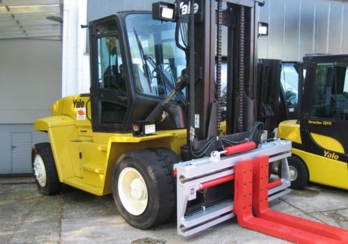
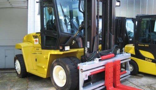
Yale D877 GLP130 EB Lift Truck Service Repair Manual

Yale D877 GLP130 EB Lift Truck Service Repair Manual

Forklift

Yale D877 GLP130 EB Lift Truck Service Repair Manual


The Yale D877 GLP130 EB Lift Truck Service Repair Manual (Europe Edition) is an essential technical document designed to provide comprehensive guidance for professional technicians, mechanics, and maintenance personnel. It contains detailed instructions, specifications, diagrams, and troubleshooting steps to ensure the safe and efficient servicing of the Yale GLP130 EB lift truck.

This manual is specifically tailored for the European version of the Yale D877 GLP130 EB model and adheres to manufacturer standards for service and repair.

Yale D877 GLP130 EB Lift Truck Service Repair Manual


📑 Manual Content Overview

The service repair manual includes the following sections:

1. General Information

  • Safety precautions and workshop guidelines

  • Vehicle identification and model specifications

  • Recommended tools and equipment

2. Scheduled Maintenance

  • Preventive maintenance procedures

  • Service intervals and inspection checklists

  • Lubrication and fluid specifications

3. Engine System

  • Engine specifications and adjustments

  • Fuel system service and repair

  • Cooling system inspection and repair

4. Transmission and Drive Unit

  • Transmission disassembly and reassembly

  • Drive shaft, axle, and differential service

  • Torque specifications and adjustments

5. Brake System

  • Hydraulic brake system service

  • Parking brake adjustment

  • Troubleshooting brake issues

6. Steering System

  • Steering gear and linkage service

  • Hydraulic steering components

  • Adjustment and alignment procedures

7. Hydraulic System

  • Hydraulic pump, valve, and cylinder servicing

  • Hose and fitting inspection

  • Hydraulic pressure testing procedures

8. Electrical System

  • Wiring diagrams and schematics

  • Battery care and charging system

  • Lighting and instrumentation repair

9. Mast and Fork Assembly

  • Mast disassembly and inspection

  • Fork alignment and wear limits

  • Chain tension adjustment

10. Troubleshooting and Diagnostics

  • Common mechanical and electrical issues

  • Step-by-step diagnostic flowcharts

  • Error codes and corrective measures

11. Technical Data and Specifications

  • Torque charts

  • Fluid types and capacities

  • Dimensions and performance specifications

Yale D877 GLP130 EB Lift Truck Service Repair Manual
FREE MANUAL DOWNLOAD
Price: $39.99

Yale D877 GLP130 EB Lift Truck Service Repair Manual


Professional Use:
This manual is intended for qualified service personnel and assumes familiarity with standard workshop practices. It ensures accurate servicing and maximizes the operational life of the Yale D877 GLP130 EB Lift Truck.

MAN Industrial Gas Engines E 0826 E 301 Service Repair Manual

MAN Industrial Gas Engines E 0826 E 301 Service Repair Manual

Engine Service Manuals

MAN Industrial Gas Engines E 0826 E 301 Service Repair Manual

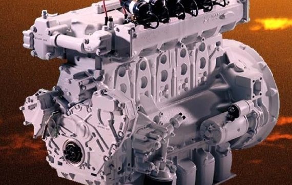
The MAN Industrial Gas Engines E 0826 and E 301 Service Repair Manual provides detailed technical information, servicing instructions, and troubleshooting procedures for professional technicians and maintenance engineers. This manual is designed to ensure reliable operation, extended engine life, and compliance with manufacturer specifications.

It is intended for qualified mechanics familiar with industrial gas engine technology and maintenance standards.


Contents of the Manual

1. Introduction

  • Purpose of the manual

  • Safety precautions and workshop guidelines

  • General information about MAN industrial gas engines

2. Technical Specifications

  • Engine design and configurations

  • Performance data (power output, fuel consumption, torque)

  • Dimensions and weight details

  • Cooling and lubrication system specifications

MAN Industrial Gas Engines E 0826 E 301 Service Repair Manual

3. Engine Identification

  • Model codes and serial number locations

  • Identification plate details

  • Variant differences (E 0826 vs. E 301)

4. Maintenance and Service Schedule

  • Recommended service intervals

  • Lubrication requirements

  • Periodic inspections and adjustments

  • Preventive maintenance practices

5. Engine Systems and Components

  • Fuel System: operation, adjustment, and servicing

  • Lubrication System: oil pump, filters, and oil circuit

  • Cooling System: radiator, water pump, and thermostat maintenance

  • Ignition and Electrical System: spark plugs, wiring diagrams, sensors

  • Air Intake and Exhaust System: filters, manifolds, and emissions control

6. Troubleshooting and Diagnostics

  • Common engine issues and fault codes

  • Systematic troubleshooting guides

  • Step-by-step diagnostic procedures

7. Disassembly and Assembly

  • Detailed engine teardown procedures

  • Replacement and reinstallation instructions

  • Torque settings and alignment specifications

8. Testing and Adjustments

  • Compression tests

  • Fuel/air ratio adjustments

  • Performance testing after service

9. Wiring Diagrams and Schematics

  • Electrical circuit diagrams

  • Control system layouts

  • Sensor and ECU connections

10. Appendices

  • Special tools list

  • Service data tables

  • Conversion charts and technical references


Applicable Models

  • MAN E 0826 Industrial Gas Engine

  • MAN E 301 Industrial Gas Engine

MAN Industrial Gas Engines E 0826 E 301 Service Repair Manual
FREE DOWNLOAD ONLINE
Price: $29.99

MAN Industrial Gas Engines E 0826 E 301 Service Repair Manual

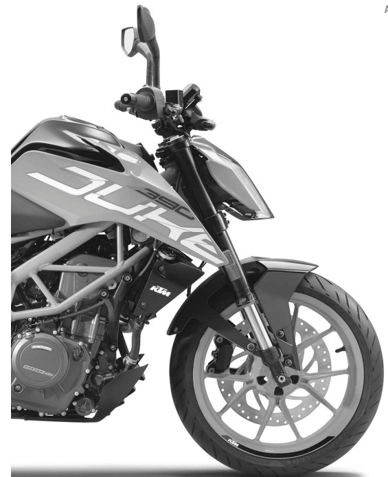
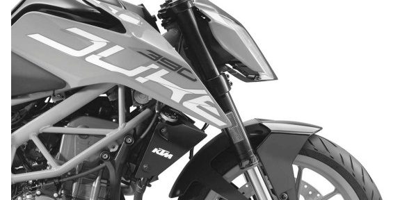
KTM 390 DUKE 2017 Service Repair Manual

KTM 390 DUKE 2017 Service Repair Manual

KTM

KTM 390 DUKE 2017 Service Repair Manual

Repair Manual Guidelines

Importance of Reading the Repair Manual

Read this repair manual carefully and thoroughly before beginning any work. The vehicle will only meet performance and reliability demands if the specified service tasks are performed regularly and correctly.

Up-to-Date Information

This repair manual has been written to reflect the latest state of this model series. Please note:

  • Technical advancements may be implemented without updating this manual immediately.

  • General workshop methods and safety rules are not described here, as they are assumed to be already known by a fully trained mechanic.

Disclaimer and Limitations

All specifications provided are non-binding. KTM Sportmotorcycle GmbH reserves the right to:

  • Modify or delete technical specifications, prices, colors, materials, services, and designs without prior notice.

  • Adapt features to meet local conditions.

  • Discontinue production of a specific model without notice.

KTM accepts no liability for delivery options, deviations from figures and descriptions, misprints, or other errors. Some models shown may include special equipment not part of the standard scope of supply.


Applicable Models

KTM 390 Duke Series

European Market

  • 390 Duke EU (F4303Q1, F4303Q2, F4303Q3, F4303Q4)

Australia

  • 390 Duke AU (F4360Q1, F4360Q2)

Japan

  • 390 Duke JP (F4386Q1, F4386Q2)

Argentina

  • 390 Duke AR (F4342Q1, F4342Q2)

Malaysia

  • 390 Duke MY (F4389Q1, F4389Q2)

Philippines

  • 390 Duke PH (F4382Q1, F4382Q2)

Thailand

  • 390 Duke TH (F4383Q4, F4383Q5)

United States

  • 390 Duke US (F4375Q1, F4375Q2)

Colombia (2018)

  • 390 Duke 2018 CO (F4341Q1, F4341Q2).

KTM 390 DUKE 2017 Service Repair Manual
FREE MANUAL DOWNLOAD
Price: $29.99

KTM 390 DUKE 2017 Service Repair Manual

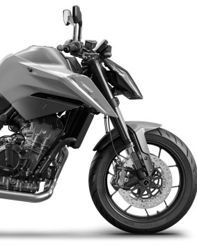
2018 KTM 790 Duke Service Repair Manual

2018 KTM 790 Duke Service Repair Manual

Ktm

2018 KTM 790 Duke Service Repair Manual

Table of Contents

1. Means of Representation – Page 7

  • 1.1 Symbols Used – 7

  • 1.2 Formats Used – 7

2. Safety Advice – Page 8

  • 2.1 Repair Manual – 8

  • 2.2 Safety Advice – 8

  • 2.3 Degrees of Risk and Symbols – 8

  • 2.4 Work Rules – 8

3. Important Notes – Page 9

  • 3.1 Manufacturer and Implied Warranty – 9

  • 3.2 Operating and Auxiliary Substances – 9

  • 3.3 Spare Parts and Accessories – 9

  • 3.4 Figures – 9

4. Serial Numbers – Page 10

  • 4.1 Type Label – 10

  • 4.2 Key Number – 10

  • 4.3 Engine Number – 10

  • 4.4 Fork Part Number – 10

  • 4.5 Shock Absorber Article Number – 11

  • 4.6 Steering Damper Article Number – 11

2018 KTM 790 Duke Service Repair Manual

5. Motorcycle – Page 12

  • 5.1 Raising the Motorcycle with the Rear Lifting Gear – 12

  • 5.2 Removing the Rear of the Motorcycle from the Lifting Gear – 12

  • 5.3 Lifting the Motorcycle with the Front Lifting Gear – 12

  • 5.4 Taking the Motorcycle off the Front Lifting Gear – 13

  • 5.5 Raising the Motorcycle with the Work Stand – 13

  • 5.6 Removing the Motorcycle from the Work Stand – 14

  • 5.7 Starting the Vehicle – 14

  • 5.8 Starting the Motorcycle to Check the Function – 15

6. Fork, Triple Clamp – Page 16

  • 6.1 Removing the Fork Legs – 16

  • 6.2 Installing the Fork Legs – 16

  • 6.3 Disassembling the Fork Legs – 19

  • 6.4 Removing the Spring – 21

  • 6.5 Checking the Fork Legs – 21

  • 6.6 Installing the Spring – 22

  • 6.12 Changing the Steering Head Bearing – 36

  • 6.13 Changing the Steering Damper – 37

  • 6.14 Cleaning the Dust Boots of the Fork Legs – 38

7. Handlebar and Controls – Page 39

  • 7.1 Checking the Free Travel of the Clutch Lever – 39

  • 7.2 Setting the Free Travel of the Clutch Lever – 39

  • 7.3 Changing the Throttle Grip – 40

8. Frame – Page 45

  • 8.1 Checking the Frame – 45

9. Shock Absorber and Swingarm – Page 46

  • 9.1 Adjusting the Spring Preload of the Shock Absorber – 46

  • 9.2 Checking the Heim Joint for Play – 46

  • 9.3 Removing the Shock Absorber – 47

  • 9.4 Installing the Shock Absorber – 48

  • 9.5 Changing the Heim Joint – 49

  • 9.6 Removing the Spring – 51

  • 9.7 Installing the Spring – 52

  • 9.8 Removing the Heim Joint – 53

  • 9.9 Installing the Heim Joint – 54

  • 9.10 Checking the Swingarm – 54

  • 9.11 Checking the Swingarm Bearing for Play – 55

  • 9.12 Removing the Swingarm – 55

  • 9.13 Changing the Swingarm Bearing – 57

  • 9.14 Installing the Swingarm – 61

10. Exhaust – Page 64

  • 10.1 Removing the Main Silencer – 64

  • 10.2 Installing the Main Silencer – 64

  • 10.3 Removing the Exhaust System – 65

  • 10.4 Installing the Exhaust System – 67

11. Air Filter – Page 71

  • 11.1 Removing the Air Filter – 71

  • 11.2 Installing the Air Filter – 72

  • 11.3 Changing the Air Filter / Cleaning the Air Filter Box – 73

12. Fuel Tank, Seat, and Trim – Page 76

  • 12.1 Opening the Filler Cap – 76

  • 12.2 Closing the Filler Cap – 76

  • 12.3 Removing the Passenger Seat – 77

2018 KTM 790 Duke Service Repair Manual
FREE MANUAL DOWNLOAD
Price: $39.00

2018 KTM 790 Duke Service Repair Manual


Posted in Ktm

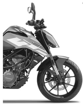
KTM 125 DUKE 2018 Repair Manual

KTM 125 DUKE 2018 Repair Manual

KTM 125 DUKE 2018 Repair Manual

Table of Contents

1. Means of Representation

1.1 Symbols Used

1.2 Formats Used

2. Safety Advice

2.1 Repair Manual

2.2 Safety Advice

2.3 Degrees of Risk and Symbols

2.4 Work Rules

3. Important Notes

3.1 Manufacturer and Implied Warranty

3.2 Operating and Auxiliary Substances

3.3 Spare Parts and Accessories

3.4 Figures

4. Serial Numbers

4.1 Chassis Number

4.2 Type Label

4.3 Key Number

4.4 Engine Number

5. Motorcycle

5.1 Raising the Motorcycle with the Rear Lifting Gear

5.2 Removing the Motorcycle from the Rear Lifting Gear

5.3 Lifting the Motorcycle with the Front Lifting Gear

5.4 Taking the Motorcycle off the Front Lifting Gear

5.5 Raising the Motorcycle with the Work Stand

5.6 Removing the Motorcycle from the Work Stand

5.7 Starting

5.8 Starting the Motorcycle for Checks

6. Fork and Triple Clamp

6.1 Cleaning the Dust Boots of the Fork Legs

6.2 Removing the Fork Legs

6.3 Installing the Fork Legs

6.4 Disassembling the Fork Legs

6.5 Checking the Fork Legs

6.6 Assembling the Fork Legs

6.7 Removing the Lower Triple Clamp

6.8 Installing the Lower Triple Clamp

6.9 Checking the Play of the Steering Head Bearing

6.10 Adjusting the Steering Head Bearing Play

6.11 Changing the Steering Head Bearing

KTM 125 DUKE 2018 Repair Manual

7. Handlebar and Controls

7.1 Checking the Play in the Throttle Cable

7.2 Adjusting the Play in the Throttle Cable

7.3 Checking the Clutch Lever Play

7.4 Adjusting the Play in the Clutch Lever

8. Frame

8.1 Changing Footrest Brackets

8.2 Checking the Frame

9. Shock Absorber and Swingarm

9.1 Measuring the Rear Wheel Dimension (Unloaded)

9.2 Checking the Static Sag of the Shock Absorber

9.3 Adjusting the Spring Preload of the Shock Absorber

9.4 Checking the Heim Joint for Play

9.5 Removing the Shock Absorber

9.6 Installing the Shock Absorber

9.7 Removing the Spring

9.8 Installing the Spring

9.9 Checking the Swingarm

9.10 Removing the Swingarm

9.11 Installing the Swingarm

9.12 Checking the Swingarm Bearing for Play

9.13 Changing the Swingarm Bearing

10. Exhaust

10.1 Removing the Exhaust System

10.2 Installing the Exhaust System

10.3 Removing the Main Silencer

10.4 Installing the Main Silencer

11. Air Filter

11.1 Changing the Air Filter and Cleaning the Air Filter Box

12. Fuel Tank, Seat, and Trim

12.1 Opening the Filler Cap

12.2 Closing the Filler Cap

12.3 Removing the Front Rider’s Seat

12.4 Mounting the Front Rider’s Seat

12.5 Removing the Passenger Seat

12.6 Mounting the Passenger Seat

12.7 Removing the Fuel Tank Cover

12.8 Installing the Fuel Tank Cover

12.9 Removing the Fuel Tank

12.10 Installing the Fuel Tank

12.11 Removing the Front Spoiler

12.12 Fitting the Front Spoiler

KTM 125 DUKE 2018 Repair Manual
FREE MANUAL DOWNLOAD
Price: $29.99

KTM 125 DUKE 2018 Repair Manual

Posted in Ktm

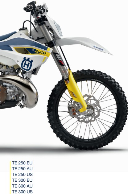
2015 Husqvarna TE 250 – 300 Service Repair Manual

2015 Husqvarna TE 250 – 300 Service Repair Manual

2015 Husqvarna TE 250 - 300 Service Repair Manual

2015 Husqvarna TE 250 – 300 Service Repair Manual

Table of Contents

1. Means of Representation

1.1 Symbols Used

1.2 Formats Used

2. Safety Advice

2.1 Repair Manual

2.2 Safety Advice

2.3 Degrees of Risk and Symbols

2.4 Work Rules

3. Important Notes

3.1 Warranty

3.2 Operating and Auxiliary Substances

3.3 Spare Parts and Accessories

3.4 Figures

4. Serial Numbers

4.1 Chassis Number

4.2 Type Label (TE EU/AU)

4.3 Engine Number

4.4 Fork Article Number

4.5 Shock Absorber Article Number

5. Motorcycle

5.1 Raising the Motorcycle with the Lift Stand

5.2 Removing the Motorcycle from the Lift Stand

5.3 Starting

5.4 Starting the Motorcycle for Checking

6. Fork and Triple Clamp

6.1 Adjusting the Compression Damping of the Fork

6.2 Adjusting the Rebound Damping of the Fork

6.3 Bleeding the Fork Legs

6.4 Cleaning the Dust Boots of the Fork Legs

6.5 Loosening the Fork Protection

6.6 Positioning the Fork Protection

6.7 Removing the Fork Legs

6.8 Installing the Fork Legs

6.9 Removing the Fork Protector

6.10 Installing the Fork Protector

6.11 Performing a Fork Service

6.12 Disassembling the Fork Legs

6.13 Removing the Spring

6.14 Disassembling the Cartridge

6.15 Disassembling the Piston Rod

6.16 Disassembling the Hydrostop Unit

6.17 Disassembling the Seal Ring Retainer

6.18 Checking the Fork Legs

6.19 Assembling the Seal Ring Retainer

6.20 Assembling the Hydrostop Unit

6.21 Assembling the Piston Rod

6.22 Assembling the Cartridge

6.23 Assembling the Fork Legs

6.24 Greasing the Steering Head Bearing

6.25 Removing the Lower Triple Clamp

6.26 Installing the Lower Triple Clamp

6.27 Checking the Play of the Steering Head Bearing

6.28 Changing the Steering Head Bearing

6.29 Adjusting the Play of the Steering Head Bearing

7. Handlebar and Controls

7.1 Handlebar Position

7.2 Adjusting the Handlebar Position

7.3 Adjusting the Basic Position of the Clutch Lever

7.4 Checking Throttle Cable Routing

7.5 Checking the Play in the Throttle Cable

7.6 Adjusting the Play in the Throttle Cable

8. Frame

8.1 Removing the Engine Guard

8.2 Installing the Engine Guard

8.3 Checking the Frame

9. Shock Absorber and Swingarm

9.1 Adjusting the High-Speed Compression Damping

9.2 Adjusting the Low-Speed Compression Damping

9.3 Adjusting the Rebound Damping

9.4 Measuring the Sag of the Unloaded Rear Wheel

9.5 Checking the Static Sag of the Shock Absorber

9.6 Checking the Riding Sag of the Shock Absorber

9.7 Adjusting the Spring Preload of the Shock Absorber

9.8 Adjusting the Riding Sag

9.9 Removing the Shock Absorber

9.10 Installing the Shock Absorber

9.11 Checking the Shock Absorber Linkage

9.12 Servicing the Shock Absorber

9.13 Removing the Spring

9.14 Disassembling the Damper

9.15 Disassembling the Piston Rod

9.16 Disassembling the Seal Ring Retainer

9.17 Changing the Pilot Bushing

9.18 Checking the Damper

9.19 Removing the Heim Joint

9.20 Installing the Heim Joint

9.21 Assembling the Seal Ring Retainer

9.22 Assembling the Piston Rod

9.23 Assembling the Damper

9.24 Bleeding and Filling the Damper

9.25 Filling the Damper with Nitrogen

9.26 Installing the Spring

9.27 Checking the Swingarm

9.28 Removing the Swingarm

9.29 Installing the Swingarm

9.30 Changing the Swingarm Bearing

10. Exhaust

10.1 Removing the Main Silencer

10.2 Installing the Main Silencer

10.3 Changing the Glass Fiber Yarn Filling in the Main Silencer

11. Air Filter

11.1 Removing the Air Filter Box Cover

11.2 Installing the Air Filter Box Cover

11.3 Removing the Air Filter

11.4 Installing the Air Filter

11.5 Cleaning the Air Filter and Air Filter Box

11.6 Sealing the Air Filter Box

2015 Husqvarna TE 250 - 300 Service Repair Manual
FREE MANUAL DOWNLOAD
Price: $39.99

2015 Husqvarna TE 250 – 300 Service Repair Manual