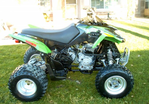
2007 ARCTIC CAT 250 DVX UTILITY ATV Service Repair Manual

2007 ARCTIC CAT 250 DVX UTILITY ATV Service Repair Manual

Artic

2007 ARCTIC CAT 250 DVX UTILITY ATV Service Repair Manual

Contents of the Service Manual

This manual is divided into organized sections that cover every aspect of the ATV:

1. General Information

  • Vehicle identification numbers

  • Safety precautions

  • Maintenance intervals

2. Engine Maintenance and Repair

  • Cylinder head disassembly/assembly

  • Piston and ring replacement

  • Valve clearance adjustment

  • Lubrication and cooling system

3. Fuel and Carburetor System

  • Fuel line inspection

  • Carburetor cleaning and tuning

  • Fuel tank servicing

4. Electrical System

  • Battery maintenance

  • Ignition system diagnostics

  • Wiring diagrams and schematics

  • Lighting system troubleshooting

5. Transmission and Drivetrain

  • Gearbox disassembly/assembly

  • Chain drive adjustment

  • Clutch inspection and repair

6. Brake System

  • Hydraulic brake servicing

  • Pad replacement procedures

  • Brake line bleeding instructions

7. Suspension and Steering

  • Front A-arm suspension setup

  • Rear swingarm and shock absorber maintenance

  • Steering adjustment and lubrication

8. Frame and Body

  • Chassis inspection

  • Body panel removal and installation

  • Fastener torque specifications

9. Troubleshooting Guide

  • Step-by-step diagnostic flowcharts

  • Common mechanical failures and fixes

2007 ARCTIC CAT 250 DVX UTILITY ATV Service Repair Manual

Service Repair Manual Covers:

General Information

Periodic Maintenance / Tune-Up

Engine / Transmission

Fuel / Lubrication / Cooling

Electrical System

Drive System

Suspension

Steering / Frame

Controls / Indicators

Aids for Maintenance

Troubleshooting

Wiring Diagrams

2007 ARCTIC CAT 250 DVX UTILITY ATV Service Repair Manual
FREE MANUAL DOWNLOAD
Price: $39.99

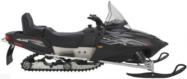
2007 POLARIS TWO STROKE SNOWMOBILE Service Repair Manual

2007 POLARIS TWO STROKE SNOWMOBILE Service Repair Manual

Polaris

2007 POLARIS TWO STROKE SNOWMOBILE Service Repair Manual

Introduction to the 2007 Polaris Two-Stroke Snowmobile Manual

The 2007 Polaris Two-Stroke Snowmobile Service Repair Manual is the definitive resource for technicians, mechanics, and owners who require accurate maintenance and repair instructions. This manual covers the entire lineup of Polaris two-stroke snowmobiles released in 2007, providing detailed service procedures, exploded diagrams, troubleshooting guides, and technical specifications essential for proper repair and upkeep.

Models Covers:

340 LX

340 Touring

Widetrak LX

500 XC SP

Super Sport

550 LX

Trail RMK

Trail Touring Deluxe

600 HO IQ

600 HO IQ Cleanfire

600 HO IQ LX Cleanfire

600 HO Switchback

600 HO Switchback Cleanfire

600 HO RMK 144/155 (F/O)

600 HO IQ Touring Cleanfire

Dragon

Dragon RMK

Service Repair Manual Covers:

Specifications

General

Maintenance

Fuel Delivery

Engine

Clutching

Final Drive & Brakes

Front Suspension & Steering

Rear Suspension

Chassis & Hood

Electrical

Index

Wiring Diagrams

2007 POLARIS TWO STROKE SNOWMOBILE Service Repair Manual

Why the Manual Is Essential for Snowmobile Owners

Proper care of a snowmobile is vital to ensure performance, safety, and longevity. This manual is designed to:

  • Provide step-by-step repair instructions for all major components.

  • Help mechanics identify issues with detailed troubleshooting sections.

  • Offer factory specifications for adjustments, torque values, and clearances.

  • Include wiring diagrams and flowcharts for accurate electrical diagnostics.

  • Guide preventive maintenance schedules to minimize costly repairs.

Whether you are a professional technician or a snowmobile owner who prefers DIY maintenance, this manual delivers comprehensive knowledge to keep your 2007 Polaris Two-Stroke in peak condition.

2007 POLARIS TWO STROKE SNOWMOBILE Service Repair Manual


Models Covered in the 2007 Polaris Two-Stroke Manual

This manual applies to a wide range of Polaris two-stroke snowmobiles manufactured in 2007, including but not limited to:

  • Polaris RMK Series

  • Polaris Dragon Series

  • Polaris Switchback Series

  • Polaris Fusion Series

  • Polaris Trail Touring and Classic Touring models


Key Sections of the Service Repair Manual

1. General Information

  • Model identification numbers

  • Safety precautions and proper workshop practices

  • Recommended tools and equipment

2. Engine Service

  • Complete teardown and rebuild procedures

  • Cylinder, piston, and crankshaft inspection

  • Carburetor and fuel injection system service

  • Cooling system maintenance and specifications

3. Chassis and Suspension

  • Front and rear suspension service

  • Shock absorber inspection and rebuilding

  • Track removal, adjustment, and replacement

  • Steering system alignment and lubrication

4. Electrical System

  • Detailed wiring diagrams

  • Ignition system testing

  • Battery and charging system checks

  • Lighting and accessory wiring

5. Transmission and Drive System

  • Chaincase service and lubrication

  • Drive belt replacement and adjustment

  • Clutch service and tuning procedures

6. Troubleshooting Guide

  • Engine starting problems

  • Poor acceleration and loss of power

  • Overheating issues

  • Electrical malfunctions

  • Vibration and noise diagnostics

2007 POLARIS TWO STROKE SNOWMOBILE Service Repair Manual
FREE MANUAL DOWNLOAD
Price: $39.99

2007 POLARIS TWO STROKE SNOWMOBILE Service Repair Manual

2010-2011 Yamaha F225, F250, F300 4-Stroke Outboard Service Repair Manual

2010-2011 Yamaha F225, F250, F300 4-Stroke Outboard Service Repair Manual

Yamaha

2010-2011 Yamaha F225, F250, F300 4-Stroke Outboard Service Repair Manual

Owning a 2010–2011 Yamaha F225, F250, or F300 4-Stroke Outboard requires access to a reliable and complete service repair manual. This comprehensive guide ensures owners, technicians, and marine mechanics can maintain, troubleshoot, and repair these powerful engines with precision.

Covers the following models:


F225CA – Code 6CL – Serial Number 1000001 and up

LF225CA – Code 6CM – Serial Number 1000001 and up

F250CA – Code 6CG – Serial Number 1000001 and up

LF250CA – Code 6CH – Serial Number 1000001 and up

F300CA – Code 6CE – Serial Number 1000001 and up

LF300CA – Code 6CF – Serial Number 1000001 and up


Importance of the Yamaha Outboard Service Manual

The Yamaha F225, F250, and F300 repair manual is the official reference for proper maintenance. It eliminates guesswork by providing factory-authorized specifications, torque values, step-by-step service instructions, and detailed diagrams. Using this manual ensures:

  • Correct troubleshooting and diagnostics.

  • Extended engine life through proper maintenance.

  • Cost savings on repairs by avoiding unnecessary replacements.

  • Safe handling of mechanical and electrical systems.


Who Needs This Manual?

  • Boat owners who want to handle regular maintenance themselves.

  • Marine mechanics and workshops servicing Yamaha 4-Stroke outboards.

  • Dealers and resellers who must keep engines in peak condition.

  • Technical training centers using it as an educational reference.


Contents of the Yamaha F225, F250, F300 Manual

The manual is divided into structured sections covering every aspect of these 2010–2011 Yamaha 4-Stroke outboards.

General Information

  • Engine specifications and identification numbers.

  • Safety instructions and workshop practices.

  • Required tools and special service equipment.

Maintenance and Adjustments

  • Periodic service schedules.

  • Lubrication points and fluid specifications.

  • Adjustment procedures for throttle, shift, and linkages.

Power Unit (Engine)

  • Complete disassembly and assembly instructions.

  • Cylinder head, block, and piston service.

  • Camshaft timing, valve clearance adjustment, and torque settings.

Fuel System

  • Fuel pump inspection and repair.

  • Injector testing and replacement.

  • Fuel line diagrams and troubleshooting fuel delivery issues.

Cooling System

  • Water pump servicing.

  • Thermostat replacement.

  • Cooling passages cleaning and inspection.

Electrical System

  • Wiring diagrams for F225, F250, and F300.

  • Starter motor, alternator, and ignition system testing.

  • Battery charging diagnostics.

Lower Unit (Gearcase)

  • Propeller shaft service.

  • Gear inspection and adjustment.

  • Oil seals replacement and lubrication procedures.

Steering and Trim System

  • Hydraulic steering service.

  • Trim/tilt motor testing.

  • Relief valve and cylinder repair.

Troubleshooting Section

  • Step-by-step diagnostic charts.

  • Engine performance issues.

  • Common fault codes and solutions.

2010-2011 Yamaha F225, F250, F300 4-Stroke Outboard Service Repair Manual
FREE MANUAL DOWNLOAD
Price: $39.99

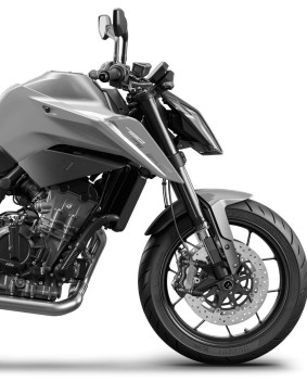
2018 KTM 790 Duke Service Repair Manual

2018 KTM 790 Duke Service Repair Manual

Ktm

2018 KTM 790 Duke Service Repair Manual

Table of Contents

1. Means of Representation – Page 7

  • 1.1 Symbols Used – 7

  • 1.2 Formats Used – 7

2. Safety Advice – Page 8

  • 2.1 Repair Manual – 8

  • 2.2 Safety Advice – 8

  • 2.3 Degrees of Risk and Symbols – 8

  • 2.4 Work Rules – 8

3. Important Notes – Page 9

  • 3.1 Manufacturer and Implied Warranty – 9

  • 3.2 Operating and Auxiliary Substances – 9

  • 3.3 Spare Parts and Accessories – 9

  • 3.4 Figures – 9

4. Serial Numbers – Page 10

  • 4.1 Type Label – 10

  • 4.2 Key Number – 10

  • 4.3 Engine Number – 10

  • 4.4 Fork Part Number – 10

  • 4.5 Shock Absorber Article Number – 11

  • 4.6 Steering Damper Article Number – 11

2018 KTM 790 Duke Service Repair Manual

5. Motorcycle – Page 12

  • 5.1 Raising the Motorcycle with the Rear Lifting Gear – 12

  • 5.2 Removing the Rear of the Motorcycle from the Lifting Gear – 12

  • 5.3 Lifting the Motorcycle with the Front Lifting Gear – 12

  • 5.4 Taking the Motorcycle off the Front Lifting Gear – 13

  • 5.5 Raising the Motorcycle with the Work Stand – 13

  • 5.6 Removing the Motorcycle from the Work Stand – 14

  • 5.7 Starting the Vehicle – 14

  • 5.8 Starting the Motorcycle to Check the Function – 15

6. Fork, Triple Clamp – Page 16

  • 6.1 Removing the Fork Legs – 16

  • 6.2 Installing the Fork Legs – 16

  • 6.3 Disassembling the Fork Legs – 19

  • 6.4 Removing the Spring – 21

  • 6.5 Checking the Fork Legs – 21

  • 6.6 Installing the Spring – 22

  • 6.12 Changing the Steering Head Bearing – 36

  • 6.13 Changing the Steering Damper – 37

  • 6.14 Cleaning the Dust Boots of the Fork Legs – 38

7. Handlebar and Controls – Page 39

  • 7.1 Checking the Free Travel of the Clutch Lever – 39

  • 7.2 Setting the Free Travel of the Clutch Lever – 39

  • 7.3 Changing the Throttle Grip – 40

8. Frame – Page 45

  • 8.1 Checking the Frame – 45

9. Shock Absorber and Swingarm – Page 46

  • 9.1 Adjusting the Spring Preload of the Shock Absorber – 46

  • 9.2 Checking the Heim Joint for Play – 46

  • 9.3 Removing the Shock Absorber – 47

  • 9.4 Installing the Shock Absorber – 48

  • 9.5 Changing the Heim Joint – 49

  • 9.6 Removing the Spring – 51

  • 9.7 Installing the Spring – 52

  • 9.8 Removing the Heim Joint – 53

  • 9.9 Installing the Heim Joint – 54

  • 9.10 Checking the Swingarm – 54

  • 9.11 Checking the Swingarm Bearing for Play – 55

  • 9.12 Removing the Swingarm – 55

  • 9.13 Changing the Swingarm Bearing – 57

  • 9.14 Installing the Swingarm – 61

10. Exhaust – Page 64

  • 10.1 Removing the Main Silencer – 64

  • 10.2 Installing the Main Silencer – 64

  • 10.3 Removing the Exhaust System – 65

  • 10.4 Installing the Exhaust System – 67

11. Air Filter – Page 71

  • 11.1 Removing the Air Filter – 71

  • 11.2 Installing the Air Filter – 72

  • 11.3 Changing the Air Filter / Cleaning the Air Filter Box – 73

12. Fuel Tank, Seat, and Trim – Page 76

  • 12.1 Opening the Filler Cap – 76

  • 12.2 Closing the Filler Cap – 76

  • 12.3 Removing the Passenger Seat – 77

2018 KTM 790 Duke Service Repair Manual
FREE MANUAL DOWNLOAD
Price: $39.00

2018 KTM 790 Duke Service Repair Manual


Posted in Ktm

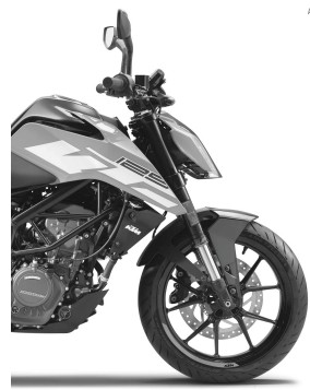
KTM 125 DUKE 2018 Repair Manual

KTM 125 DUKE 2018 Repair Manual

KTM 125 DUKE 2018 Repair Manual

Table of Contents

1. Means of Representation

1.1 Symbols Used

1.2 Formats Used

2. Safety Advice

2.1 Repair Manual

2.2 Safety Advice

2.3 Degrees of Risk and Symbols

2.4 Work Rules

3. Important Notes

3.1 Manufacturer and Implied Warranty

3.2 Operating and Auxiliary Substances

3.3 Spare Parts and Accessories

3.4 Figures

4. Serial Numbers

4.1 Chassis Number

4.2 Type Label

4.3 Key Number

4.4 Engine Number

5. Motorcycle

5.1 Raising the Motorcycle with the Rear Lifting Gear

5.2 Removing the Motorcycle from the Rear Lifting Gear

5.3 Lifting the Motorcycle with the Front Lifting Gear

5.4 Taking the Motorcycle off the Front Lifting Gear

5.5 Raising the Motorcycle with the Work Stand

5.6 Removing the Motorcycle from the Work Stand

5.7 Starting

5.8 Starting the Motorcycle for Checks

6. Fork and Triple Clamp

6.1 Cleaning the Dust Boots of the Fork Legs

6.2 Removing the Fork Legs

6.3 Installing the Fork Legs

6.4 Disassembling the Fork Legs

6.5 Checking the Fork Legs

6.6 Assembling the Fork Legs

6.7 Removing the Lower Triple Clamp

6.8 Installing the Lower Triple Clamp

6.9 Checking the Play of the Steering Head Bearing

6.10 Adjusting the Steering Head Bearing Play

6.11 Changing the Steering Head Bearing

KTM 125 DUKE 2018 Repair Manual

7. Handlebar and Controls

7.1 Checking the Play in the Throttle Cable

7.2 Adjusting the Play in the Throttle Cable

7.3 Checking the Clutch Lever Play

7.4 Adjusting the Play in the Clutch Lever

8. Frame

8.1 Changing Footrest Brackets

8.2 Checking the Frame

9. Shock Absorber and Swingarm

9.1 Measuring the Rear Wheel Dimension (Unloaded)

9.2 Checking the Static Sag of the Shock Absorber

9.3 Adjusting the Spring Preload of the Shock Absorber

9.4 Checking the Heim Joint for Play

9.5 Removing the Shock Absorber

9.6 Installing the Shock Absorber

9.7 Removing the Spring

9.8 Installing the Spring

9.9 Checking the Swingarm

9.10 Removing the Swingarm

9.11 Installing the Swingarm

9.12 Checking the Swingarm Bearing for Play

9.13 Changing the Swingarm Bearing

10. Exhaust

10.1 Removing the Exhaust System

10.2 Installing the Exhaust System

10.3 Removing the Main Silencer

10.4 Installing the Main Silencer

11. Air Filter

11.1 Changing the Air Filter and Cleaning the Air Filter Box

12. Fuel Tank, Seat, and Trim

12.1 Opening the Filler Cap

12.2 Closing the Filler Cap

12.3 Removing the Front Rider’s Seat

12.4 Mounting the Front Rider’s Seat

12.5 Removing the Passenger Seat

12.6 Mounting the Passenger Seat

12.7 Removing the Fuel Tank Cover

12.8 Installing the Fuel Tank Cover

12.9 Removing the Fuel Tank

12.10 Installing the Fuel Tank

12.11 Removing the Front Spoiler

12.12 Fitting the Front Spoiler

KTM 125 DUKE 2018 Repair Manual
FREE MANUAL DOWNLOAD
Price: $29.99

KTM 125 DUKE 2018 Repair Manual

Posted in Ktm

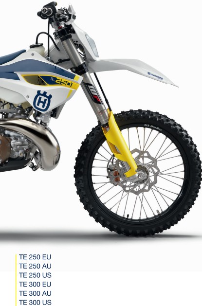
2015 Husqvarna TE 250 – 300 Service Repair Manual

2015 Husqvarna TE 250 – 300 Service Repair Manual

2015 Husqvarna TE 250 - 300 Service Repair Manual

2015 Husqvarna TE 250 – 300 Service Repair Manual

Table of Contents

1. Means of Representation

1.1 Symbols Used

1.2 Formats Used

2. Safety Advice

2.1 Repair Manual

2.2 Safety Advice

2.3 Degrees of Risk and Symbols

2.4 Work Rules

3. Important Notes

3.1 Warranty

3.2 Operating and Auxiliary Substances

3.3 Spare Parts and Accessories

3.4 Figures

4. Serial Numbers

4.1 Chassis Number

4.2 Type Label (TE EU/AU)

4.3 Engine Number

4.4 Fork Article Number

4.5 Shock Absorber Article Number

5. Motorcycle

5.1 Raising the Motorcycle with the Lift Stand

5.2 Removing the Motorcycle from the Lift Stand

5.3 Starting

5.4 Starting the Motorcycle for Checking

6. Fork and Triple Clamp

6.1 Adjusting the Compression Damping of the Fork

6.2 Adjusting the Rebound Damping of the Fork

6.3 Bleeding the Fork Legs

6.4 Cleaning the Dust Boots of the Fork Legs

6.5 Loosening the Fork Protection

6.6 Positioning the Fork Protection

6.7 Removing the Fork Legs

6.8 Installing the Fork Legs

6.9 Removing the Fork Protector

6.10 Installing the Fork Protector

6.11 Performing a Fork Service

6.12 Disassembling the Fork Legs

6.13 Removing the Spring

6.14 Disassembling the Cartridge

6.15 Disassembling the Piston Rod

6.16 Disassembling the Hydrostop Unit

6.17 Disassembling the Seal Ring Retainer

6.18 Checking the Fork Legs

6.19 Assembling the Seal Ring Retainer

6.20 Assembling the Hydrostop Unit

6.21 Assembling the Piston Rod

6.22 Assembling the Cartridge

6.23 Assembling the Fork Legs

6.24 Greasing the Steering Head Bearing

6.25 Removing the Lower Triple Clamp

6.26 Installing the Lower Triple Clamp

6.27 Checking the Play of the Steering Head Bearing

6.28 Changing the Steering Head Bearing

6.29 Adjusting the Play of the Steering Head Bearing

7. Handlebar and Controls

7.1 Handlebar Position

7.2 Adjusting the Handlebar Position

7.3 Adjusting the Basic Position of the Clutch Lever

7.4 Checking Throttle Cable Routing

7.5 Checking the Play in the Throttle Cable

7.6 Adjusting the Play in the Throttle Cable

8. Frame

8.1 Removing the Engine Guard

8.2 Installing the Engine Guard

8.3 Checking the Frame

9. Shock Absorber and Swingarm

9.1 Adjusting the High-Speed Compression Damping

9.2 Adjusting the Low-Speed Compression Damping

9.3 Adjusting the Rebound Damping

9.4 Measuring the Sag of the Unloaded Rear Wheel

9.5 Checking the Static Sag of the Shock Absorber

9.6 Checking the Riding Sag of the Shock Absorber

9.7 Adjusting the Spring Preload of the Shock Absorber

9.8 Adjusting the Riding Sag

9.9 Removing the Shock Absorber

9.10 Installing the Shock Absorber

9.11 Checking the Shock Absorber Linkage

9.12 Servicing the Shock Absorber

9.13 Removing the Spring

9.14 Disassembling the Damper

9.15 Disassembling the Piston Rod

9.16 Disassembling the Seal Ring Retainer

9.17 Changing the Pilot Bushing

9.18 Checking the Damper

9.19 Removing the Heim Joint

9.20 Installing the Heim Joint

9.21 Assembling the Seal Ring Retainer

9.22 Assembling the Piston Rod

9.23 Assembling the Damper

9.24 Bleeding and Filling the Damper

9.25 Filling the Damper with Nitrogen

9.26 Installing the Spring

9.27 Checking the Swingarm

9.28 Removing the Swingarm

9.29 Installing the Swingarm

9.30 Changing the Swingarm Bearing

10. Exhaust

10.1 Removing the Main Silencer

10.2 Installing the Main Silencer

10.3 Changing the Glass Fiber Yarn Filling in the Main Silencer

11. Air Filter

11.1 Removing the Air Filter Box Cover

11.2 Installing the Air Filter Box Cover

11.3 Removing the Air Filter

11.4 Installing the Air Filter

11.5 Cleaning the Air Filter and Air Filter Box

11.6 Sealing the Air Filter Box

2015 Husqvarna TE 250 - 300 Service Repair Manual
FREE MANUAL DOWNLOAD
Price: $39.99

2015 Husqvarna TE 250 – 300 Service Repair Manual

2014 Husqvarna FE 250 Service Repair Manual

2014 Husqvarna FE 250 Service Repair Manual

Motorcycle

2014 Husqvarna FE 250 Service Repair Manual

Table of Contents

1. Means of Representation

1.1 Symbols Used

1.2 Formats Used

2. Safety Advice

2.1 Repair Manual

2.2 Safety Advice

2.3 Degrees of Risk and Symbols

2.4 Work Rules

3. Important Notes

3.1 Manufacturer and Implied Warranty

3.2 Operating and Auxiliary Substances

3.3 Spare Parts and Accessories

3.4 Figures

4. Serial Numbers

4.1 Chassis Number

4.2 Type Label (FE 250 EU/AU)

4.3 Key Number (FE 250 EU/AU)

4.4 Engine Number

4.5 Fork Part Number

4.6 Shock Absorber Article Number

5. Motorcycle

5.1 Raising the Motorcycle with a Lift Stand

5.2 Removing the Motorcycle from the Lift Stand

5.3 Starting

5.4 Starting the Motorcycle for a Check

6. Fork, Triple Clamp

6.1 Adjusting the Compression Damping of the Fork

7. Handlebar and Controls

7.2 Adjusting the Handlebar Position

7.3 Adjusting the Basic Position of the Clutch Lever

7.4 Checking the Routing of the Throttle Cable

7.5 Checking the Play in the Throttle Cable

7.6 Adjusting the Play in the Throttle Cable

8. Frame

8.1 Removing the Engine Guard

8.2 Installing the Engine Guard

8.3 Checking the Frame

9. Shock Absorber, Swingarm

9.1 Adjusting the High-Speed Compression Damping

9.2 Adjusting the Low-Speed Compression Damping

9.3 Adjusting the Rebound Damping

9.4 Measuring Rear Wheel Sag (Unloaded)

9.5 Checking the Static Sag of the Shock Absorber

9.6 Checking the Riding Sag of the Shock Absorber

9.7 Adjusting the Spring Preload

9.8 Adjusting the Riding Sag

9.9 Removing the Shock Absorber

9.10 Installing the Shock Absorber

9.11 Checking the Shock Absorber Linkage

2014 Husqvarna FE 250 Service Repair Manual
FREE DOWNLOAD YOUR EMAIL
Price: $29.99